![]()
![]()
by
Wenton L. Davis
![]()
![]()
Whew! By now, you should have a moderately decent knowledge of how SPICE works and how to define and simulate a circuit. There is one very important way of using spice that doesn't really fit in to using the commands, but is vital for some operations. The ability to define and use subcircuits in SPICE keeps some circuits from being incredibly complex.
In the basics page, I touched briefly on the use of a subcircuit, using a subcircuit to emulate an op-amp. The first example was an extremely simplistic circuit:
.SUBCKT OPAMP1 1 2 6
RIN 1 2 10MEG
EP1 3 0 1 2 100K
RP1 3 4 1K
CP1 4 0 1.5915UF

EOUT 5 0 4 0 1
ROUT 5 6 1
.ENDS
In this incredibly simplistic op-amp, the non-inverting input is node 1, the inverting input is node 2, and the output is node 6. It is very important to note that when using subcircuits, the subcircuit node numbers are NOT related to the node numbers in the top-level circuit. (Node 0 is always "ground" though.) This circuit basically uses a very high-value input resistor between the non-inverting and inverting input nodes, simulating Rin≈∞. A dependent voltage source, EP1 simulates an extremely high gain, passing through a low-pass filter, RP1 and CP1, which does a pretty poor job of emulating the gain-bandwidth product of most amplifiers, but at least it provides the extremely high gain. Finally, the output is derived from another depenent voltage source EOUT passing through a very low output resistor, simulating Rout≈0.
Although this subcircuit is a poor representation of a real op-amp, it can be used repeatedly as a single line in a SPICE circuit, rather than having to define all 6 components for each op-amp in a circuit.
Consider the circuit:
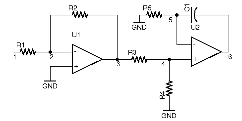
Using the subcircuit above, we can define the circuit:
Vin 1 0 DC 0 AC 1
R1  1 2 1K
R2  2 3 1K
R3  3 4 1K
R4  4 0 1K
R5  5 0 1K
C1  5 6 1u
XU1 0 2 3 OPAMP1
XU2 5 4 6 OPAMP1
![]()
![]()
![]()