![]()
![]()
Working with the 1541 Disk Drive
by
Wenton L. Davis
![]()
![]()
This little project was a lot of "fun." For
anyone familiar with some of the more modern computers being able
to access the older Commodore drives, you know that cbm4linux was
adopted into a new project known as
OpenCBM. Opencbm is
really an interesting project. The biggest trick to it is
knowing which cable you want to build, first. Yes, I said
"build." There are places you can buy them, but in many
cases, no one is building them, any more. I suppose that is
because the ZoomFloppy is more readily available and works great,
but, I'm getting ahead of the story. Let's back up a bit,
first.
Part one: The original interface
The first time I tried the cbm4linux project, it
was still common to find computers and even laptops with the old
DB25 printer connector. Yes, it was that long ago!
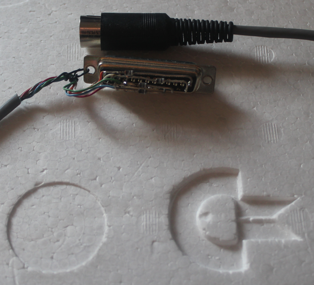
For this device, there are 4 diodes used to
protect the parallel port... or do they protect the 1541? Maybe
both. The original cable did not use diodes, called the
X1541, but the addition of these diodes produced the XM1541
cable. Later, the XA1541 cable ("active") replaced the diodes
with transistor invertors. Then, the XE1541 cable comes
along, moving one of the diodes, but otherwise the same as the
XM1541.
In the mean time, a parallel cable is introduced,
connecting the 1541 to the Commodore's USER port, basically
connecting one of the Commodore's VIA chips to one of the 1541's
VIA chips. This allows software like Dolphin DOS and Speed
DOS to communicate with the 1541 much much faster than the
standard serial port. The 1541 needs to be opened up, some
rather tricky soldering to one of the VIA chips, with some ribbon
cable, and viola!, parallel cable. As the X*1541 cable
family grew, this became known as the XP1541. This will be
discussed in more depth, later.
Well, time passes, as it will, and the parallel
port becomes harder to find, while the evil Darth USB comes along
and takes over. As a result, the XU1541 is a USB dongle with
a 6-pin DIN cable sticks out the other end. By this time,
cbm4linux has been fully absorbed into opencbm, and ports for
Micr$oft Windoze are becoming available, although I've never
managed to get it running, yet. (I need to remove the old
libusb0 and install libusb1, but that's a project for the
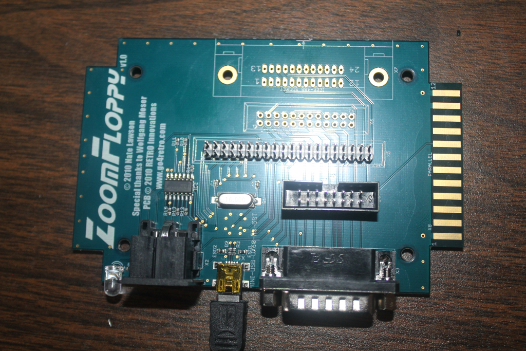
future.) Eventually, there is a new family member
introduced, the XUM1541, pronounced "zoom 1541." Well, the
guys at Retro Innovations take that and step it up to a device
called "ZoomFloppy." The ZoomFloppy is capable of talking to
the 1541 via the standard serial port, and can optionally include
the parallel cable. ZoomFloppy also has the additional
ability to have an IEEE488 port added so it can communicate with
the 4040 and 8050 and similar drives. The version I got does
not have the centronics port for the IEEE488 bus, but all I need
to do is order the connector and solder it on.
Step two: Using opencbm
Opencbm comes with lots of tools, perhaps most
importantly are d64copy and cbmctrl. In order to use the
tools, the source code has to be compiled. Part of the
configure process (before compiling) is to know which cable
(mentioned above) is going to be used. I won't go into all
the details, here, but the compilation depends on which cable is
used, and if you want to change to a different cable, it is
necessary to uninstall, rebuild, then reinstall. (I hope the
folks at opencbm find a way to not go through the rigmarole, but
that's the way it is for now.)
So probably the first thing to do once opencbm is
installed is to see if the PC can see the external 1541(s).
This is done with the command:
cbmctrl detect
Now, if all is working correctly, you should see
something like this:
8: 1541C
This shows you that device 8, one of the more
common 1541 devices, the 1541C, has been detected.
Now here's where things get interesting.
There are several flavors of 1541 drives. The original was
actually the original 1540 drive. (I think this is actually
the VIC1541, but I can't validate this information; I'd appreciate
it if anyone could.) Next, the 1541 comes along. These
two devices will report this way (assuming it is device 8):
8: 1540 or 1541
Next, along comes the enhanced version of the
1541, named the 1541C. I assume there was a 1541A and a
1541B, but I only found limited references to the 1541B, which
apparently still reports itself as a 1541C, so I would guess the
a541A and 1541B never saw the market? If the drive is device
9, it would report this way:
9: 1541C
Finally, we come across the 1541-II drive, which
reports device 10 as
10: 1541-II
And of course, device 11 is also always
available.
Now, there are lots of ways to use cbmctrl, and
I'm not going to go into the details for all of them.
Suffice to say you can send all the IEC bus messages like TALK,
UNTALK, LISTEN, UNLISTEN, and so on. One particularly useful
command is
cbmctrl dir 8
Which will grab the directory off of the disk in
drive 8. Although most of the opencbm commands default to
drive 8, cbmctrl seems to need you to tell it which device to talk
to.
Formatting a disk is also very easy with the
command
cbmformat "label,AA" 8
where AA can be any two-character tag, just like
the format command from the Commodore computers.
Step three: Using ViCE
Another really impressive project is the Virtual
Commodore Emulator, or "ViCE." ViCE is available for Linux
and Windoze, and I believe it is available on Macs as well.
This package provides emulators for the VIC-20, Commodore 64, Pet,
Plus 4, Commodore 128, and a number of other systems, some of
which may not have existed. There is an xscpu64 which seems
like a Commodore 64 with a 16 (or 20?)-MHz processor, based on the
65812 CPU. (16M RAM, but BASIC only uses the same amount as
the standard C64.)
The emulators also use virtual disk drives, which
can be 1541s, 1571s, or several other disk drive types.
These drives use files on the host machine called D64 files.
These files, named something like diskimage.d64, are byte-for-byte
images of the 35 tracks on a standard disk from a 1541
drive. There is no compression, so each D64 file is always
174848 bytes long. For the most part, they work very well.
There are also some interesting tools in the ViCE
package. One of these is vsid, which I have not played with
much, yet, but another is c1541, a tool for looking at d64
images. When the 1541 drives were first opened, they had a
utility disk that came with them so you could display specific
track/sectors or view the block availability map (BAM). The
c1541 utility allows you to do essentially the same thing.
It takes some time to learn the commands, but it is a very useful
tool for manipulating d64 images.
The really nice tool that comes with opencbm that
reads a physical disk in the 1541 drive and created a .d64 image
is d64copy. In order to make a .d64 image, you can simply
type the command
d64copy 8 mydisk.d64
One really nice feature is that you can also
write a .d64 image back to a physical disk. Simply use the
command
d64copy mydisk.d64 8
The d64copy program provides a nice display to
the screen, showing which track and sector has just been
completed. This allows the user to see that something is
actually happening.
Step four: .d64 shortcomings
Well, using d64 images in ViCE normally works
very well. You can even set the emulator so that it makes
the same sounds as the 1541 drives including the spinning spindle
and head movements. (And frankly, the sound effects are
surprisingly accurate!)
But then, there are the issues most of us
remember, copy-protection. Many of us remember these as the
awful head-grinding sound the 1541 made, saying, "Oh crap! that
didn't work!" And of course, our best friend for making...
uhm... "backup" copies of these disks was the Fast Hackem
disks. I don't know that anyone ever had an original Fast
Hackem disk... it just kind of spread itself around.
Copy protection most commonly came in one of two
forms: 1) half-track data where data was stuck on a "hidden"
track, halfway between two other regular tracks, and 2) sectors
were intentionally written with bad checksums, so that when a disk
was copied, it would either fail to read the sector correctly, or
it would correct the checksum on the copied disk, which the
software would then know was a copy instead of an original.
Well, Fast Hackem incorporated something called a "nibbler," which
would detect and duplicate these defects and half-tracks, and
correctly (or "incorrectly," depending on how you look at it)
reproduced these copy protection schemes.
.d64 images, however, do not include sector
checksums or half track data. As a result, the .d64 images
are not going to include any of the information, so programs that
use these schemes are going to fail, just as if the disks were
illegal copies made without our good friend, Fast Hackem.
The problem here is - there were a lot of popular
games for the Commodore computers that were copy-protected, and
these games will not work in ViCE when the disk drive emulator is
using a .d64 image. This becomes very disappointing.
But there is a solution, the .g64 image.
The .g64 image stores all of the disk image in GCR, much more like
the physical disk. .g64 images can also contain half-track
data as well as potentially invalid checksums. .g64 images
are not generated by d64copy, though. In order to generate
.g64 images, it is necessary to build and install nibtools, which
is essentially an add-on for opencbm.
Step five: Using nibtools
Now we want to use nibtools to create .g64
images. This sounds simple enough at first. Compiling
nibtools was a little tougher than I anticipated because it is not
a stand-alone package. The source code has to be placed very
carefully inside the directory structure where opencbm was, and it
has to be in just the right spot, or it will fail to find the
necessary files, and will fail to compile.
Once nibtools has been compiled and installed, we
type the command similar to d64copy:
nibread gauntlet
This will generate the files gauntlet.log and
gauntlet.nbz if all goes well. Well, the first time I tried,
all did not go well. Up to this point, using the XUM1541 has
been working just fine with the simple 6-pin serial cable.
Nibtools, however is far more extensive, and requires both the
serial AND the parallel cables to be installed.
DIRTY WORDS!
So, I create a shopping list and make a quick
trip to my good friend, DigiKey.com. A few days later, we
have all the parts. (HINT: DO NOT cheap-out on parts.
Working with pristine new parts will be much easier.)
Step six: Building the parallel cable
At this point, I'll point out that I am not a
mechanical person. Wiring a circuit is one thing, building a
mechanical device is not among my talents, so this was not easy
for me.
I read lots of websites talking about building
the parallel cable, and they all made it sound like "you just..."
at each step. There is no "just" in any of this. One
of the big issues I found was the instructions usually said to
solder the parallel cable (presumably ribbon cable) directly to
the 6522 VIA chip. I can not strongly enough discourage this
practice. The older MOS chips are still sensitive enough
that the pins that have no connection to anything are still
terribly sensitive to static discharge. Instead, plan on a
40-pin socket as the intermediary between the 6522 and it's host
socket on the board inside the 1541.
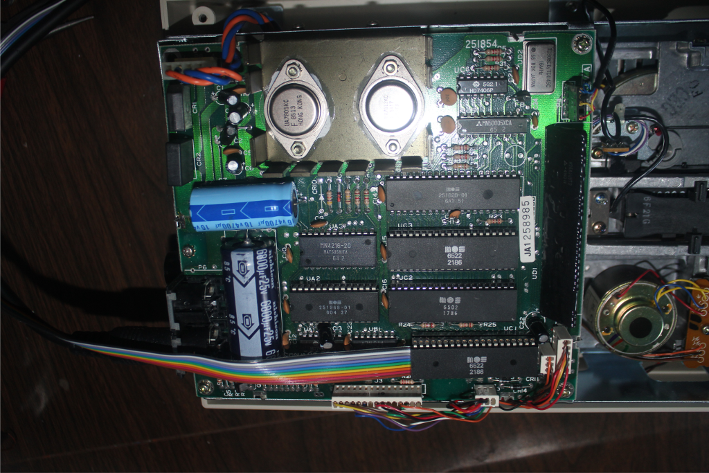
OK, so let's open op the 1541 and see what we
have, here.
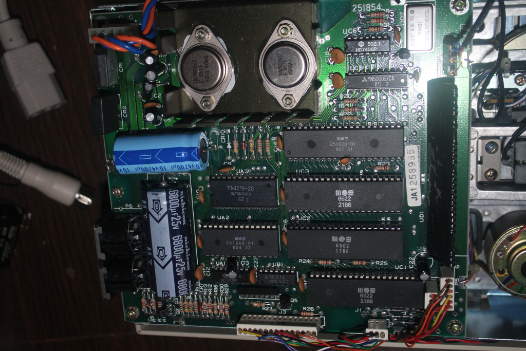
Now, many of the instructions on websites said
that the VIA chip we are interested in is labelled "U2." But
looking at the picture above, I found that the chip labelled "UC2"
is the 6502.... the main CPU, not the VIA. Next, we discover
that there are two VIA chips. (I knew this would be the
case, before-hand.) So, we are faced with the question,
which one is the one I care about? In this case, we have UC1 and
UC3 to chose from. I also know that pin 2 of the chip we
care about is used in 1541C versions as a sensor for track 1 on
the disk, so I know there is a trace I will have to cut. It
also turns out that I'll have to replace the ROM, but I'll deal
with that later.
So which one, which one? I know! I'll just look
up the schematic diagram for a 1541C disk drive. I should
have known this was not going to be easy. Remember that the
instructions said to look for the chip labelled "U2" as the chip
we cared about, and then we find that chip UC2 is the CPU? This
should have been a bit more of a clue that there were variations
of the controller board. I guess I knew that, but I was not
ready for how widely the variations would spread. Searching
for the 1541C schematic resulted in dozens of variations, and the
chip labeling was different in every one of them. If you
look very closely at the top of the board, there is the number
251854 printed in the silkscreen. It didn't help at all.
I finally found a schematic for one of the 1541B
versions, and the chip numbering seemed at least close to the
labeling I was seeing on the board I was looking at. This
allowed me to conclude that UC1 was probably the one I cared
about, and J1 and J2, which define the hardware bits identifying
the drive as 8, 9, 10, or 11, was also right next to this chip,
and the schematic showed these connected to the same chip I was
interested in. UC1 is apparently the one I want, but I'll
proceed slowly since I'm not 100% sure.
So, I carefully remove the 6522 from its
socket. This was not made easy by C22 and the 3-pin header
connector, but I managed, and eventually, I got the chip out and
placed it in a static-pad. (Again, these chips are very
sensitive to static discharge, so don't leave it just laying
around.) A quick look underneath reveals:
I think I see which trace is going to be pin 2,
but I'm not completely sure, so I scrape just a little of the
green coating off to expose the trace. I was about to
connect my ohm-meter, when I suddenly thought, "wait! What if I'm
wrong, and I am about to throw voltage into a circuit filled with
static-sensitive parts?" So, I decided on another path. I
connected my signal generator through a small piece of wire into
pin 2 of the socket. I set the amplitude at 0.1VPP, so I was
not going to be hitting any inputs too hard. then I probed
the copper trace with my oscilloscope, and BINGO! Pin 2! I
also knew that pin 2 of the chip I cared about was connected to
pin 10 of UC6, which is located all the way on the opposite end of
the board. I put my 'scope probe on pin 10, and looky there!
I have my signal again. I can now be sure that I have
selected the correct VIA, and I have located the trace that I need
to cut. So...

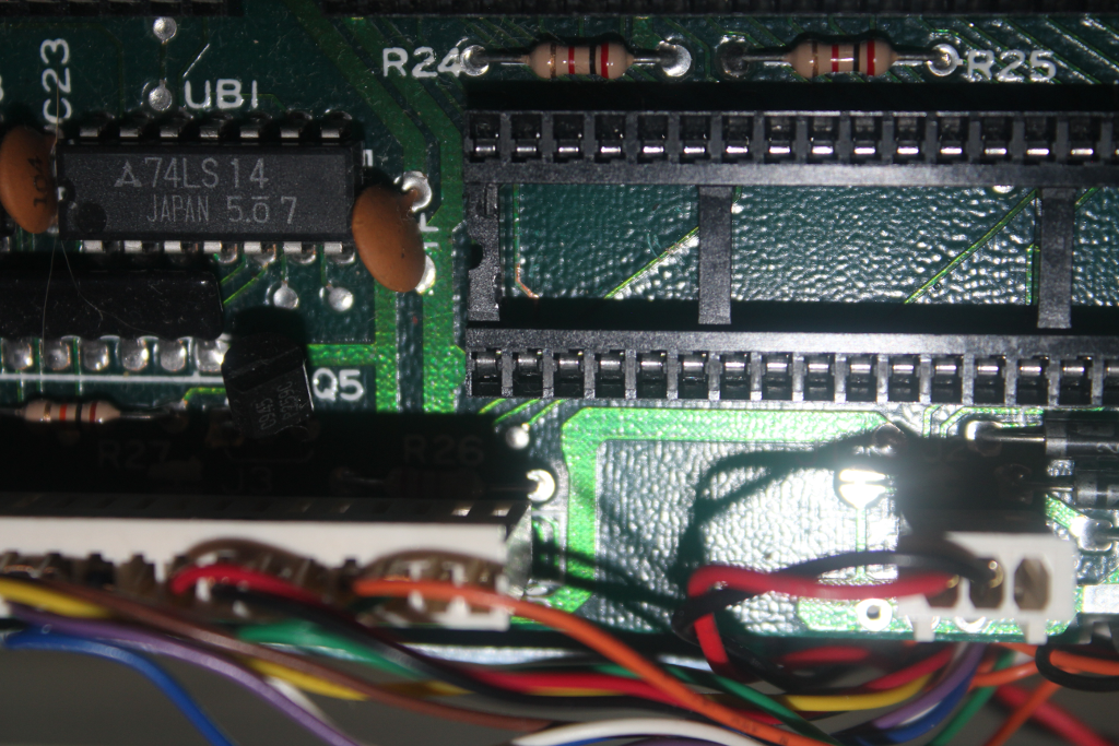
Sorry the important part is so blurry - the
camera insisted on focusing on the socket. But the trace is
cut, now.
OK, that was the easy part. (Yes,
everything is relative.) Now for the messy part. Now
to build the parallel cable between the ZoomFloppy and the
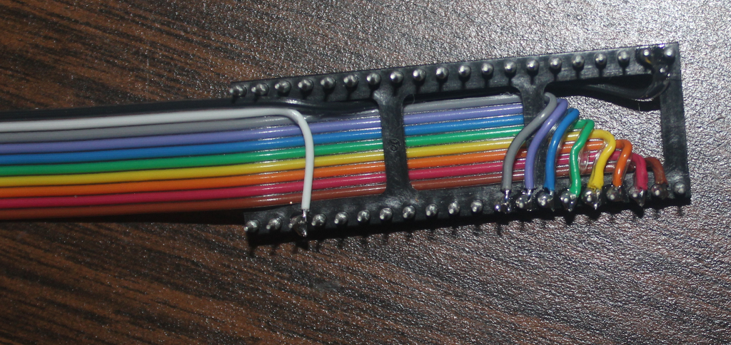
1541. As I mentioned before, I strongly recommend putting a
socket between the 6522 VIA and the socket on the controller board
over soldering directly onto the chip. The opposite end of
the cable soldered to the DB15 was easy, and because the ribbon
cable is already color-coded 1-9, then black for 10, and I need
pins 1-10 of the DB15 connector, I decided to use the color-coding
to relate to the DB15 connector. This meant be very careful
connecting to the pins on the socket. Now, before anyone
yells ate me that I didn't orient the 40-pin socket correctly (180
degrees around), yeah, I know. I realized that just as I was
almost finished, and It was easier to just move on anyway.
So, after a long time, I completed the socket-end:
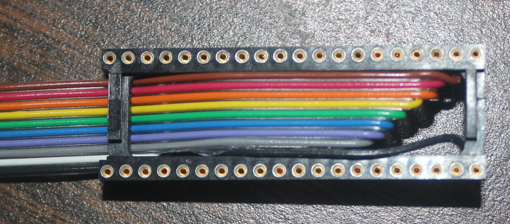
Now at this point, I realized that I also had the
cable pointing out of the socket in the wrong direction.
"Well rats!" But I'm OK with this because I am really big
into relieving stress on the cables when I can, so I fold the
cable over the top of the socket, and put the 6522 chip into the
socket, pinning the ribbon cable down. The completed
assembly ends up looking like this:
assembly.png
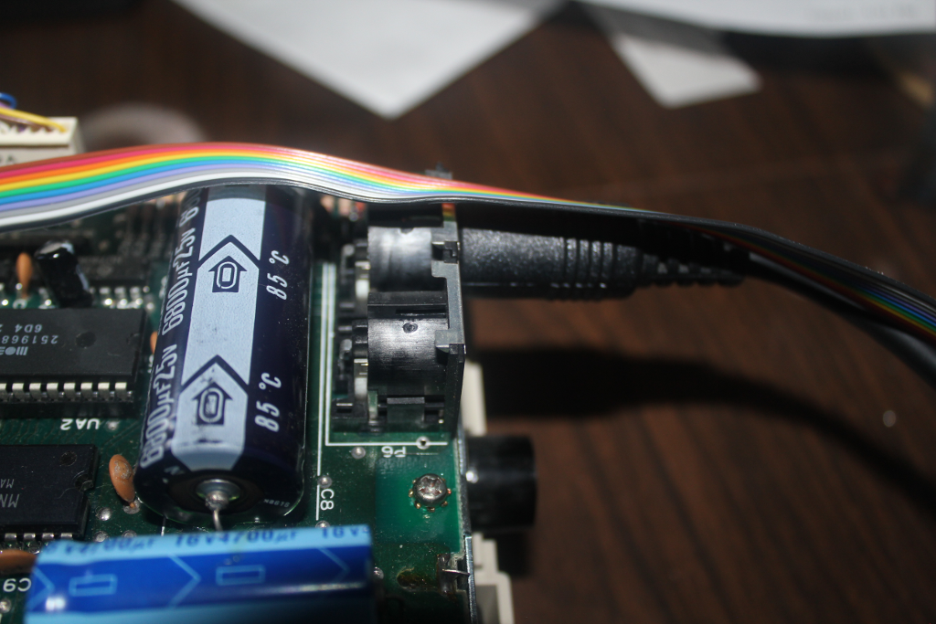
And then I move it back onto the 1541controller
board:
I was really happy with this result, the cable is
almost perfectly centered over the serial port cable connector:
At this point, I decide that I can close it all
up, again. But I make a rather disappointing discovery: I
forgot that the case only provides a small hole for the serial
cable. My earlier excitement about the ribbon cable being
right on top of the serial port connector was replaced by
disappointment that I could not do anything at this point to feed
the cable through that small hole without rebuilding the whole
cable. So, I slip the ribbon cable out the seam between the
halves of the 1541 drive.
However, hefore I can close it all up, I have to
replace the ROM. You see, that trace from pin 2 that had to
be cut is used by 1541C drives to sense track 1 of the disk.
(I'm not sure how this is done, but it is a feature of the 1541C
drive, and since I have no older 1540 or 1541 drives, I have to
deal with this. Now, because I have cut this wire, I now can
not use the 1541C ROM. The 1541C ROM is actually two
halves.. the DOS portion and the KERNEL portion. In 1540 and
1541 originals, these two sections were actually stored in a pari
of 8K ROMS, but the 1541C has both of these portions in a single
16K ROM, a 27128 chip. The first portion exists from $C000
to $DFFF, and the other portion is from $E000 to $FFFF. (In
fact crossing rom $DFFF to $E000 is actually a two-byte
instruction, where the opcode in in $DFFF and the operand is in
$E000, so it doesn't hurt anything to put them into one chip.)
So, off to find the ROM codes. It turns out
that there were multiple versions of the ROMs, just like there
were multiple of the schematics. Apparently, I also have the
option of using the ROMS from the 1541-II version, so that will be
plan B. Eventually, I find a pair of files that contain the
code from $C000 to $DFFF, and from $E000 to $FFFF. I combine
them from a pair of 8K files into a single 16K file.
Now begins the quest. I had not anticipated
needing to replace the ROMs, so I did not order a nice clean 27128
chip when I ordered the rest of the parts. It took a while,
but I found a UVEPROM from an old project ("Old" as in 1995 or
so.) I also found my old UV eraser, so the chip goes into
the eraser, I set the time, and hope the bulb is still good.
35 minutes later, BZZZZzzzz! I get the chip out, and put it into
the chip programmer - I start with a "blank check," and low and
behild, the chip is clean! The chip is also NOT a 27128; it is a
27256. I look and look, and I know I have a 27128 somewhere,
but I sure can't find it. So, I look up the pinout of the
27256 and the only difference is that the A14 pin on the 27256 is
the same pin as the program pulse on the 27128. A quick
review if the schematic shows taht this pin is tied to +5V on the
board, so I know the chip will think that A14 is always
high. This means that I need to put the code ito the upper
16K instead of the lower 16K. I decided that the easiest way
to accomplish this is to make a 32K image where the upper and
lower 16K halves are the same 16K. I program the chip, put
it into the socket (I put the original ROM into a static pad and
hide it inside the case of the 1541 so if I ever want to revert it
back to a 1541C, I still have the ROM, but yes, I will need to
re-connect that line to pin 2 underneath the 6522 chip.
Now for the first real test... I close the 1541
up, apply power, and the drive powers up, runs the spindle for a
moment, with the "active" LED on, then after the drive spindle
stops and the LED turns off, I know the device is functioning.
Step seven: Back to nibtools
OK, the drive appears to be working, so I
reconnect it to the ZoomFloppy, and I run the cbmctrl detect
command, the the drive (device 8) now identifies itself as a 1541
instead of a 1541C. Then, for the last real test, I use the
cbmctrl dir 8 command to make sure the drive can find the right
track (track 18) for the directory, and it works!
So I can finally hope for the nibtools version of
d64copy to work:
nibread good_disk
This time, rather than complain about the
parallel cable missing, it seems to read the entire disk. So
far, so good. I am not reading a copy-protected disk, just a
plain old data disk, and it seems to read OK.
First, here is the output from the d64copy
attempt:
       1: *********************
       2: *********************
       3: *********************
       4: *********************
       5: *********************
       6: *********************
       7: *********************
       8: *********************
       9: *********************
      10: *********************
      11: *********************
      12: *********************
      13: *********************
      14: *********************
      15: *********************
      16: *********************
      17: *********************
      18: *******************
      19: *******************     57%   395/683[Warning] read error: 14/08: 5
      19: *******************
      20: --------?----------     57%   396/683[Warning] read error: 14/09: 5
      20: --******??---------     59%   403/683[Warning] read error: 14/0c: 5
      20: --******??--?------     59%   404/683[Warning] read error: 14/0d: 5
      20: --******??--??*----     59%   406/683[Warning] read error: 14/0f: 5
      20: --******??--??*?---     59%   407/683[Warning] read error: 14/10: 5
      20: --******??--??*??--     59%   408/683[Warning] read error: 14/11: 5
      20: --******??--??*???-     59%   409/683[Warning] read error: 14/00: 3
      20: ?-******??--??*???-     60%   410/683[Warning] giving up...
      20: ?-******??--??*???-
      21: *******************
      22: *******************
      23: *******************
      24: *******************
      25: ******************
      26: ******************
      27: ******************
      28: ******************
      29: ******************
      30: ******************
      31: *****************
      32: *****************
      33: *****************
      34: *****************
      35: *****************       99%   679/683
      671 blocks copied.
Notice how track 20 (hex 0x14) had lots of
errors; most of these are checksum errors, but sector 0 had a
different error. (I can't find any information on error
3.) Also, as we should expect, the disk was read from track 1
through 35. This is the published standard for CBM disks.
So now to try the copy-protected Gauntlet disk...
nibread gauntlet
gives us:
       1.0: (3) 7673 [CBM OK] (weakgcr:2)
       2.0: (3) 7673 [CBM OK] (weakgcr:2)
       3.0: (3) 7672 [CBM OK] (weakgcr:2)
       4.0: (3) 7672 [CBM OK] (weakgcr:2)
       5.0: (3) 7673 [CBM OK] (weakgcr:2)
       6.0: (3) 7672 [CBM OK] (weakgcr:2)
       7.0: (3) 7672 [CBM OK] (weakgcr:2)
       8.0: (3) 7672 [CBM OK] (weakgcr:1)
       9.0: (3) 7673 [CBM OK] (weakgcr:2)
      10.0: (3) 7672 [CBM OK] (weakgcr:2)
      11.0: (3) 7672 [CBM OK] (weakgcr:2)
      12.0: (3) 7673 [CBM OK] (weakgcr:2)
      13.0: (3) 7673 [CBM OK] (weakgcr:2)
      14.0: (3) 7673 [CBM OK] (weakgcr:2)
      15.0: (3) 7673 [CBM OK] (weakgcr:2)
      16.0: (3) 7673 [CBM OK] (weakgcr:2)
      17.0: (3) 7673 [CBM OK] (weakgcr:2)
      18.0: (2) 7139 [CBM OK] (weakgcr:2)
      20.0: (2) 7144 [NDOS]
            (2) 7144 [NDOS]  (weakgcr:244)
      21.0: (2) 7137 [CBM OK] (weakgcr:2)
      22.0: (2) 7137 [CBM OK] (weakgcr:2)
      23.0: (2) 7136 [CBM OK] (weakgcr:2)
      24.0: (2) 7138 [CBM OK] (weakgcr:2)
      25.0: (1) 6668 [CBM OK] (weakgcr:2)
      26.0: (1) 6667 [CBM OK] (weakgcr:1)
      27.0: (1) 6666 [CBM OK] (weakgcr:2)
      28.0: (1) 6668 [CBM OK] (weakgcr:1)
      29.0: (1) 6667 [CBM OK] (weakgcr:1)
      30.0: (1) 6668 [CBM OK] (weakgcr:1)
      31.0: (0) 6233 [CBM OK] (weakgcr:1)
      32.0: (0) 6232 [CBM OK] (weakgcr:1)
      33.0: (0) 6235 [CBM OK] (weakgcr:1)
      34.0: (0) 6234 [CBM OK] (weakgcr:1)
      35.0: (0) 6235 [CBM OK] (weakgcr:2)
      36.0: (2!=0) 7138 [CBM OK] (weakgcr:2)
      37.0: (2!=0) 7136 [CBM OK] (weakgcr:2)
      38.0: (2!=0) 7137 [CBM OK] (weakgcr:2)
      39.0: (2!=0) 7137 [CBM OK] (weakgcr:2)
      40.0: (2!=0) 7136 [CBM OK] (weakgcr:1)
      41.0: (1!=0) 0 [Unformatted Track]
      Converting to NIB format...
      Successfully parsed data to NIB format
      Successfully saved file gauntlet.nbz
In this case, nibtools identified the error in track 20, and it
also managed to find that there was information on tracks 36, 37,
38, 39, and 40.
OK, so I have this file, gauntlet.nbz. The ViCE emulators will not read .nbz files, so I have to convert it to a .g64 image, which the emulator will read. *pause*
Well that was disappointing. The emulator shows which track and sector is being read. It is getting stuck on track 20 sector 0. This is the same track and sector that had error 3 instead of error 5.
I reset the emulator, and set the speed to 10% insead
of 100%. Once the program loads, it reads track 20, sector 0 and
gets stuck. This still enforces the idea that track 20, sector 0
is part of the copy protection.
the next day...
So there I was, minding my own business, reading the nibtools documentation, when I stuble across this little tidbit:
-px Used for V-MAX disks to remaster track 20 properly.
Well, since the loading screen was black with the word "VMAX!" in the center, staring at track 20 not loading, I'm pretty sure this is the option I want. OK, let's try this then:
nibread -px gauntlet
and all I get is a listing of command-line options, indicating that -px is not a valid option for nibread. I re-read the instructions to make sure it wasn't one of the other utilities in the nibtools package. Nope, nibread and nibwrite. So, I'll try to write a new disk using the -px option, and see if tha physical C64 likes the copied disk.
*pause*
Nope, that didn't work, either. I guess it's back to more traditional cracking techniques for this one.
Conclusion
Well, it didn't work the way I'd hoped, but I was still able to build the parallel cable for nibtools to work, so it was still a marginally successful exercise.
In addition, I tried nibread with -h on another disk, Arkanoid II, and although most of the half-tracks were unformatted, I found that most of the half tracks 19.5 and higher are formatted, so I tried to write it to a blank disk to test that, and I get a segfault from nibwrite. I am assuming nibtools formats each track as it writes, but hard to be sure.
(a few hours later)
Well, the arkanoid II disk g64 image does work in ViCE. Go figure!
![]()
![]()
![]()